TITAN Command
Ready to go?
Before you begin, remove the TITAN Command device and the following accessories from the package:
- TITAN Command device
- 1 DC power input connector
- 1 DIO connector
- 1 mounting bracket 6 M4 × 6mm screws
- QR code for Quick Start Guide
Note: The following items are required for installation but are not included in the package:
- 4 × M6 screws (to secure the device to your installation location)
- External GPS antenna (required if GPS location data is desired)
- SIM cards are pre-installed if data services have been ordered from Dejero
- Otherwise, Nano SIM cards (size 4FF. Industrial-grade recommended for extended temperature range support)
SIM and Antenna requirements
The TITAN Command features integrated internal cellular and Wi-Fi antennas. However, you must install SIM cards and an external GPS antenna (if location data is required).
GPS Antenna notes
- When connecting the GPS antenna, follow the manufacturer’s instructions.
- The TITAN device supports Untethered Dead Reckoning (UDR) and Automotive Dead Reckoning (ADR).
- For UDR: Locate the antenna near the TITAN device.
- For ADR: Locate both the TITAN and the antenna near the wheel supplying speed pulses.
Insert SIM cards
To take advantage of the integrated cellular modems, you must insert SIM cards.
- Ensure the device is powered off.
- On the back of the TITAN device, remove the SIM card cover.
- Insert nano SIM cards into the slots.
- Reattach the SIM card cover.
Mount the TITAN Command
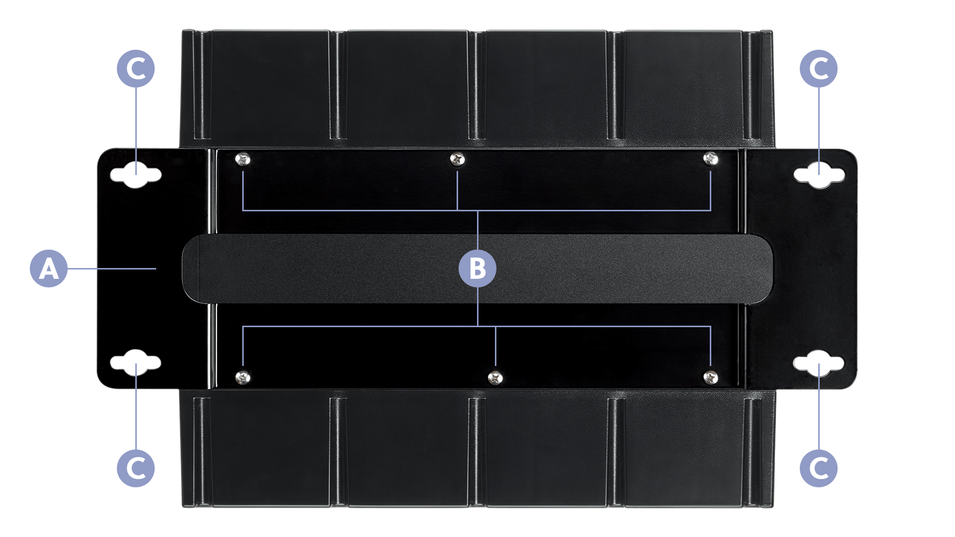
A. Align the mounting bracket on the bottom of the device with the installation location.
B. Using the supplied six M4 × 6mm screws, attach the bracket to the base of the TITAN device.
C. Secure the bracket to the installation location with four M6 screws (not included) through the keyhole openings. Tighten all screws.
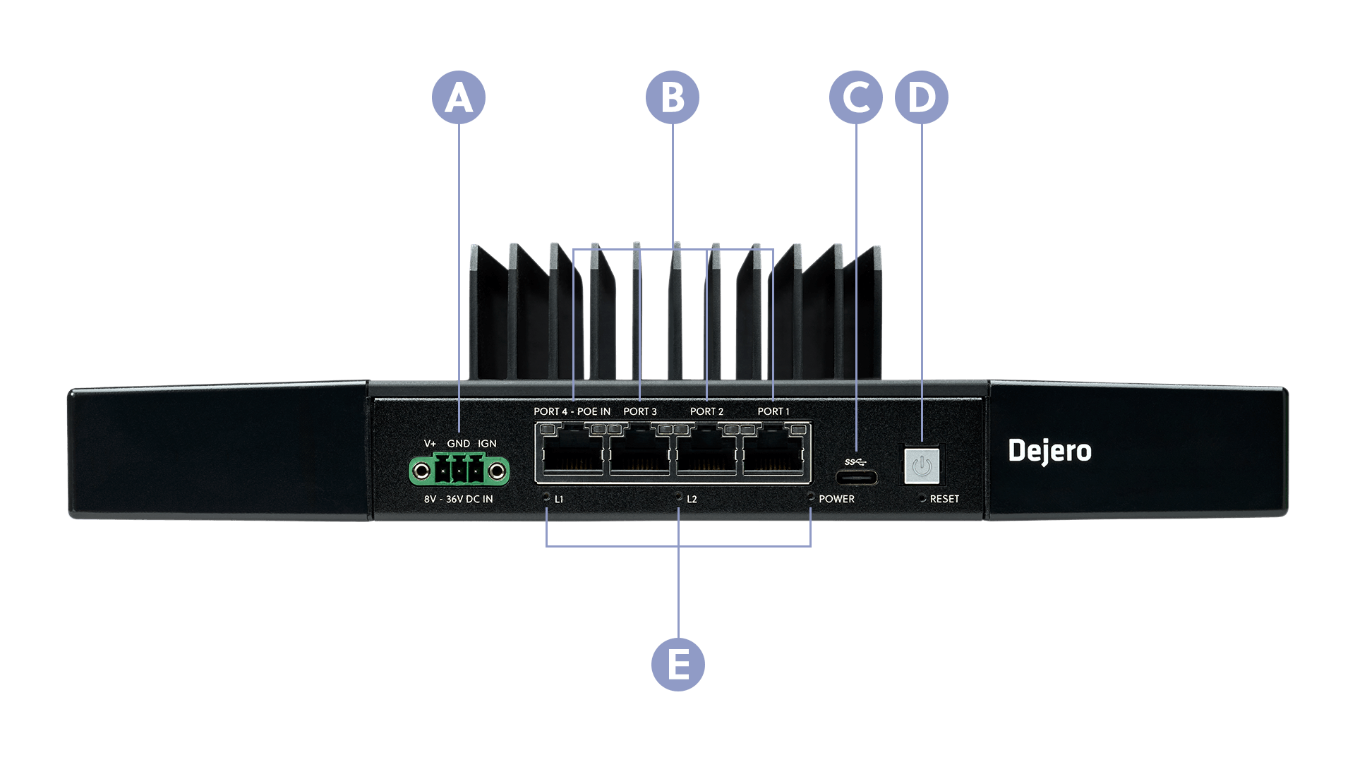
A. DC Power Port with Optional IGN Input
B. 4 × RJ-45 2.5 Gigabit Ethernet 1, 2 and 3: WAN, 4: LAN/POE++
C. USB-C Port
D. Power Button
E. 3 × LEDs: L1, L2, Power
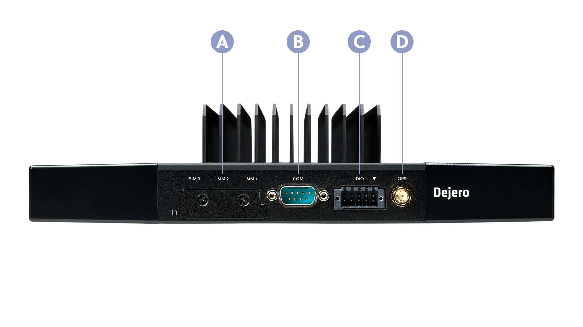
A. SIM Cover
B. Serial (COM) Port
C. DIO Port
D. GPS Antenna Port
Install the TITAN Command
For more information, visit support.dejero.com to read the Dejero TITAN Command User Guide
Connect GPS

Screw the external GPS antenna to the SMA connector on the back of the device (Port I). Tighten the SMA connector of the RF cable, not the hex lock nut on the chassis.
Prepare Power
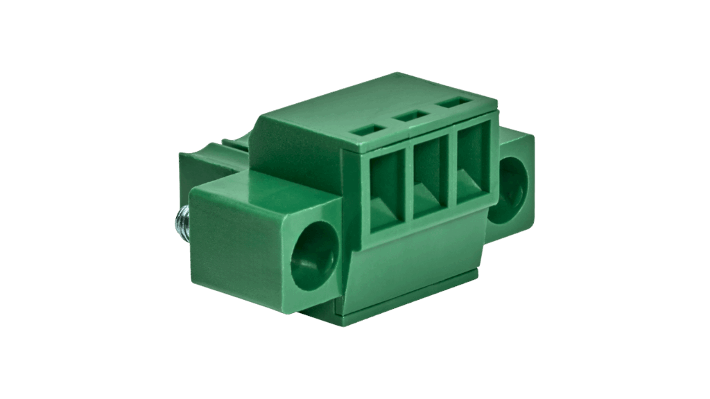
Insert wires into the mating power connector and tighten the clamping screws.
- Pin 1 (Left): V+ (8 – 36 VDC)
- Pin 2 (Middle): GND
- Pin 3 (Right): IGN (Optional – for vehicle ignition signal)
Connect Power
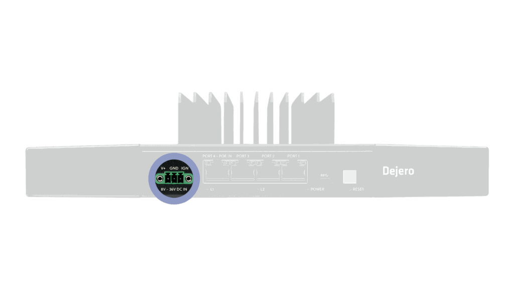
Plug the power connector into the DC Power Port (Port A) on the front of the TITAN device. Tighten the screws with a flat head screwdriver to secure it.
- Alternative: You can also power the device via POE++ using Ethernet Port 4.
Connect Network Cables
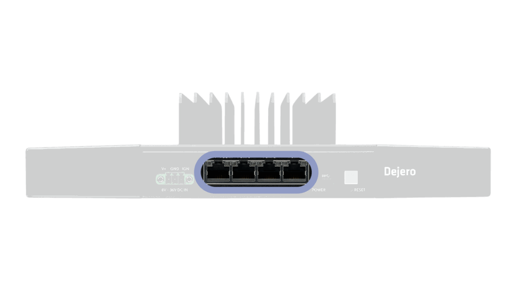
- WAN: Connect Ethernet cables to Ports 1, 2, or 3 to access the internet.
- LAN: Connect an Ethernet cable to Port 4 to connect local devices.
DIO (Optional)
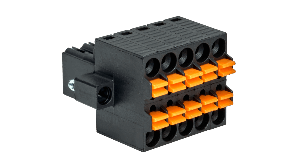
If using Digital Input/Output, insert wired ferrules into the DIO connector (Port H) by depressing the orange plunger with a screwdriver. The plunger pin stays low with the ferrule in place.
Using the TITAN Command
Upon applying power, the TITAN Command device turns on automatically and runs through the startup process.
- Power On: Press and hold the Power Button for a minimum of 2 seconds.
- Power Off: Press and hold the Power Button for a minimum of 2 seconds.
- Reboot: Press and hold the Power Button for a minimum of 10 seconds.
- The Power LED will indicate Green if the unit is powered on and will be off if no power is applied.
- The L1 LED will indicate the current operational condition of the TITAN Command device. The State indicated correlates with the Status indicated in the Control web portal.
Note: The L2 LED is reserved for future use and is not currently operational.
LED action table
| LED | State | Explanation |
|---|---|---|
| Off | INITIALIZING | The device has not connected to Control |
| Blinking Green | CONNECTING | The device is attempting to connect to Control |
| Solid Green | CONNECTED | The device is connected and operational |
| Blinking Red | DISCONNECTED | The device is connected but is experiencing an issue the concentrator. (Please contact Dejero support) |
| Solid Red | ERROR | The device is connected but is not operational. (Please contact Dejero support) |
Configure the TITAN Command
After installing the TITAN device, log into Dejero Control as an administrator to configure and manage the device.
- In a browser, visit control.dejero.com.
- Log in with your email and password.
- Configure your device settings remotely.
Need help?
You can find more support information on the SupportHub at support.dejero.com. If you require additional help, please contact support at support@dejero.com.
Technical Support:
support@dejero.com
US & Canada (Toll Free): 1 866 808 3665, ext 2
International: +1 519 772 4824, ext 2