GateWay 211 / 212
Ready to go?
Before you begin, remove the Dejero GateWay 211 or Dejero GateWay 212, the DC power input connector, and the remote power switch connector from the package.
To secure the GateWay device to your installation location, use six M4 screws. These screws are not included with the device.
External antennas are also required for the GateWay device, but they are not included, and you must purchase them separately. For more information on the recommended antennas, visit support.dejero.com to read the Dejero GateWay 211 / 212 Antenna Reference Guide.
Caution: There is a risk of explosion if the battery is replaced with an incorrect type. The GateWay device should only be serviced by authorized Dejero personnel.
Antenna requirements
The Dejero GateWay 211 / 212 requires the following external antennas:
- Six cellular (4G/LTE) antennas.
- One active GPS/GNSS antenna.
- Three Wi-Fi® antennas. All Wi-Fi antennas must be RP-SMA.
Installation notes
- When installing multiple antennas, you must maintain at least 20 cm (8 inches) between each one.
- Follow the manufacturer’s instructions for information on installing the antennas.
- When installing the antennas, consider the location where you plan to install the GateWay device. The RF cables from the antennas must reach the GateWay device easily and must be routed properly.
Antenna configurations
Use one of the following recommended configurations to select and install the antennas for the GateWay.
Warning: Single port cellular antennas can connect to any antenna port, but you must connect dual port cellular antennas to the antenna port pairs specified below. The antenna can only engage when you use these connection pairs.
Configuration option 1 (Single port antennas):
- Use one active GNSS antenna (for GPS/GLONASS and other navigation systems.) Connect the antenna to the port marked GPS.
- Use three Wi-Fi antennas. Connect each one to the available antenna ports marked W1, W2, W3.
- Use six single port antennas. Connect each one to an available antenna port (C1, C2, C3, C4, C5, C6).
Configuration option 2 (Dual port antennas):
- Use one active GNSS antenna (for GPS/GLONASS and other navigation systems.) Connect the antenna to the port marked GPS.
- Use three Wi-Fi antennas. Connect each one to the available antenna ports marked W1, W2, W3.
- Use three dual port antennas. Connect each one to the following antenna port pairs: (C1 and C2) (C3 and C4) (C5 and C6).
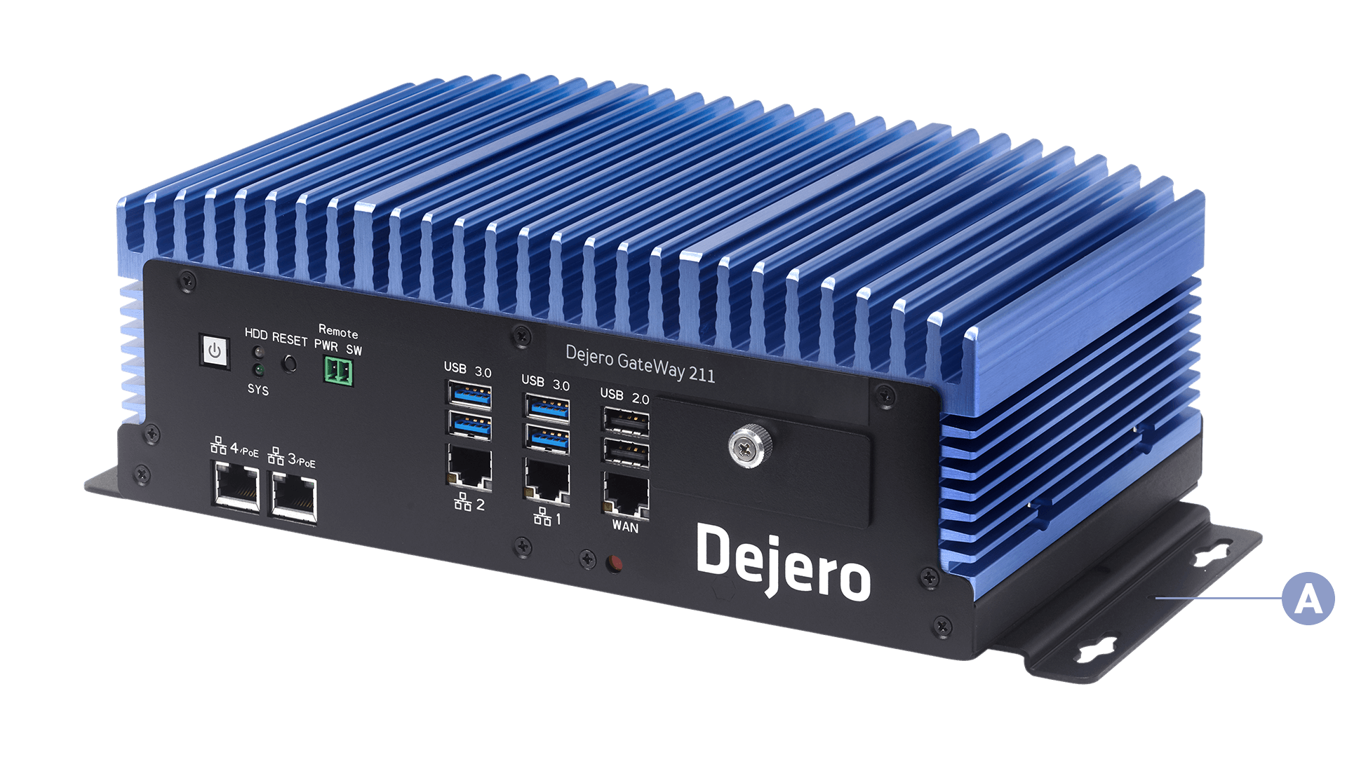
A. Mounting bracket
Mount the GateWay device
- Align the mounting bracket on one side of the device with the installation location.
- Secure the bracket to the installation location using three M4 screws.
- Repeat steps 1 and 2 with the mounting bracket on the other side of the device.
- Tighten all screws.
Set up the GateWay device
After installing the GateWay device, you must set it up.
- Screw the antennas to the SMA connectors on the back of the GateWay device. Make sure that the tool engages the SMA connector on the RF cable, not the hex lock nut on the chassis.
- Verify that you connected the active GPS antenna to the correct connector.
- If necessary, connect the power cable to the power adapter.
- Plug the power connector into the back of the GateWay device.
- Hand-tighten the connector screws.
- Verify that your power source and fuse are adequate to meet the maximum power specifications.
- Plug the power cable into a power source.
- If necessary, perform the following actions:
- To connect to a LAN, connect an Ethernet cable to Ethernet port 1, 2, 3, or 4 on the front of the GateWay device. Add a label to indicate that the cable is for the LAN connection.
- To connect to a WAN, connect an Ethernet cable to the WAN port on the front of the GateWay device. Add a label to indicate that the cable is for the WAN connection.
- To connect the additional Ethernet ports, connect Ethernet cables to the ports on the front of the device. Add a label to each cable to indicate the connection for that cable.
- If you want to configure the device using the GateWay User Interface and you want to use a monitor with this tool, connect the monitor to the HDMI port on the back of the device. Connect a keyboard and mouse to the USB ports on the front of the device. Alternatively, you can connect these peripherals using a KVM switch.
Note: Ethernet ports 3 and 4 are power over Ethernet (PoE) ports. If you want to provide power to network interfaced equipment over Ethernet, connect the device to an Ethernet cable that is connected to port 3 or 4.
For more information, visit support.dejero.com to read the Dejero GateWay 211 / 212 User Guide.
About the GateWay device
Without a monitor attached, when you press the Power button, the GateWay device runs through the startup process and establishes its connections.
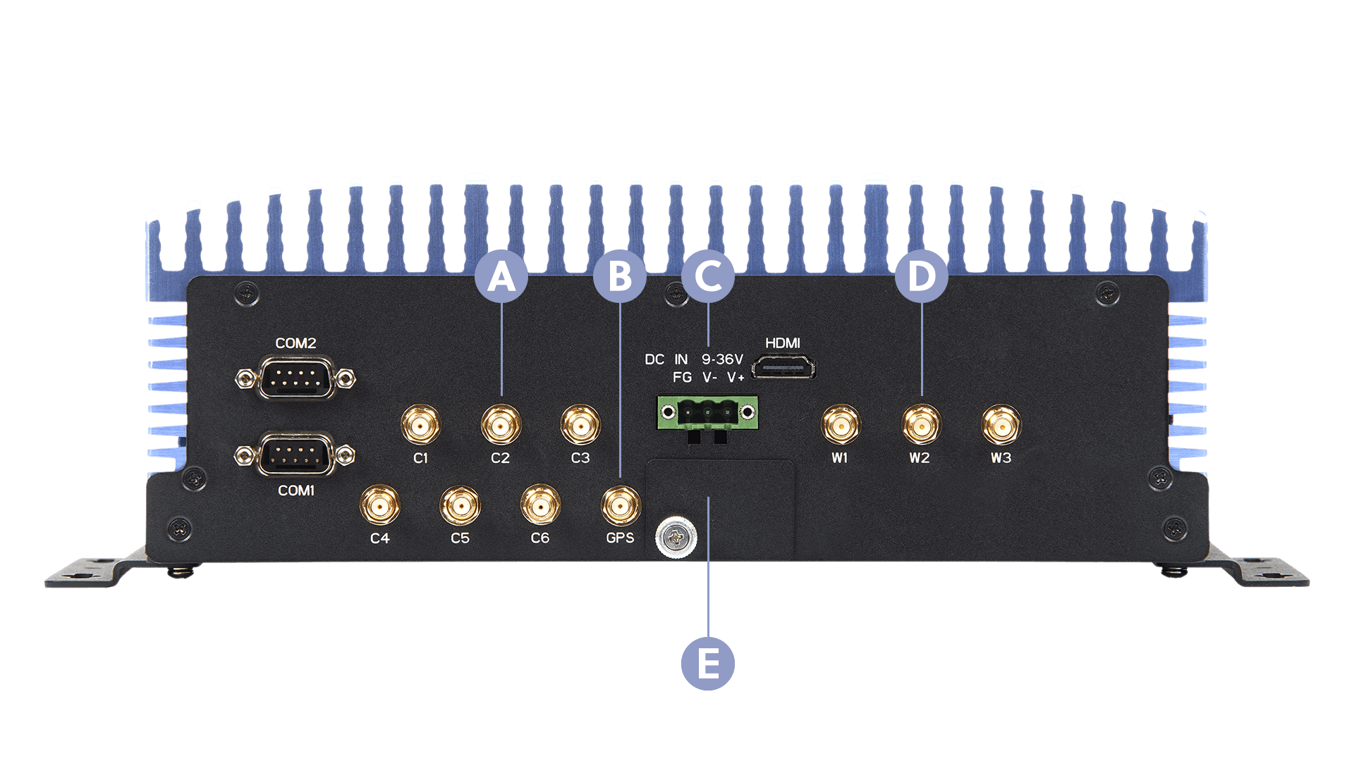
A. Antenna connectors
B. GPS connector
C. Power
D. Wi-Fi antenna connectors
E. Configuration switches
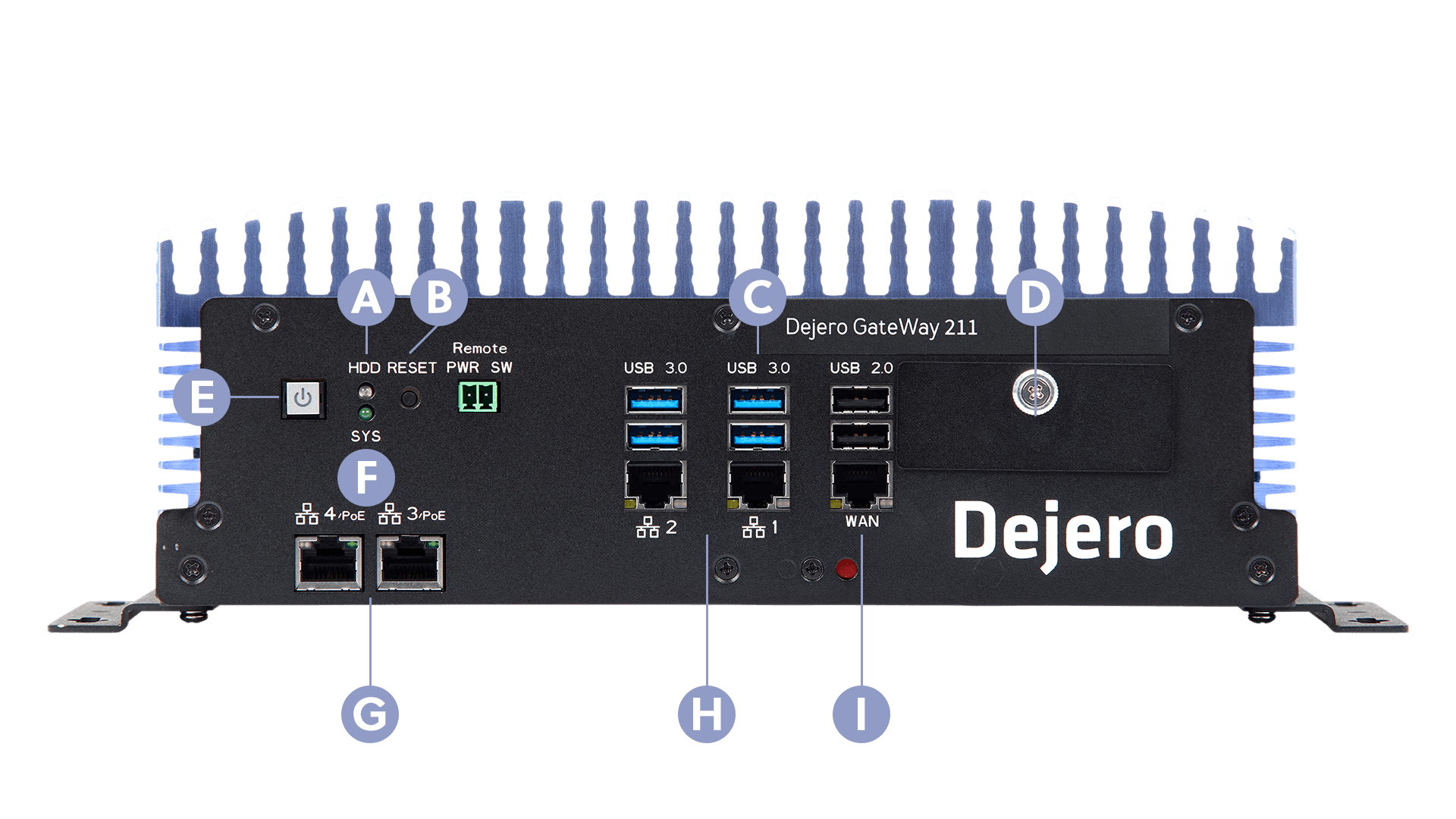
A. Hard disk activity light
B. Reset button
C. USB ports
D. SIM card cover
E. Power button
F. Power light
G. Power over Ethernet (PoE) ports
H. Additional Ethernet ports
I. WAN port
Configure the GateWay device
After installing the GateWay device, log into Dejero Control as an administrator to configure and manage the device. Then, connect other devices to it (using the LAN or WAN ports or Wi-Fi) to access the internet. For more information, visit support.dejero.com to read the Dejero GateWay 211 / 212 User Guide.
Need help?
You can find more support information on the SupportHub at support.dejero.com. If you require additional help, please contact support at support@dejero.com.
Technical Support:
support@dejero.com
US & Canada (Toll Free): 1 866 808 3665, ext 2
International: +1 519 772 4824, ext 2