GateWay M6E6 / M6E6F
Ready to go?
Before you begin, remove the GateWay device and the following accessories from the package:
- One AC power cord
- Mini-Circuits® tool
- Two mounting rails
- Two L-brackets
- Four 6-32 rail screws
- Six 6-32 chassis mount screws
- Adhesive plastic hanger for Mini-Circuits tool
Note: External antennas are also required for the GateWay device, but they are not included, and you must purchase them separately. For more information on the recommended antennas, visit support.dejero.com to read the Dejero GateWay M6E6 / M6E6F Antenna Reference Guide.
Antenna requirements
The Dejero GateWay M6E6 / M6E6F requires the following external antennas:
- Twelve cellular (4G/LTE) antennas.
- One active GPS/GNSS antenna.
- Two Wi-Fi® antennas. All Wi-Fi antennas must be RP-SMA.
Installation notes
- When installing multiple antennas, you must maintain at least 20 cm (8 inches) between each one.
- Follow the manufacturer’s instructions for information on installing the antennas.
- When installing the antennas, consider the location where you plan to install the GateWay device. The RF cables from the antennas must reach the GateWay device easily and must be routed properly.
Antenna configurations
Use one of the following recommended configurations to select and install the antennas for the GateWay.
Warning: Single port cellular antennas can connect to any antenna port, but you must connect dual port cellular antennas to the antenna port pairs specified below. The antenna can only engage when you use these connection pairs.
Configuration option 1 (Single port antennas):
- Use one active GNSS antenna (for GPS/GLONASS and other navigation systems.) Connect the antenna to the port marked GPS.
- Use two single port Wi-Fi antennas or one dual port Wi-Fi antenna. Connect each one to the available antenna ports marked Wi-Fi.
- Use twelve single port antennas. Connect each one to an available antenna port (A1, A2, A3, A4, A5, A6, A7, A8, A9, A10, A11, A12).
Configuration option 2 (Dual port antennas):
- Use one active GNSS antenna (for GPS/GLONASS and other navigation systems.) Connect the antenna to the port marked GPS.
- Use two single port Wi-Fi antennas or one dual port Wi-Fi antenna. Connect each one to the available antenna ports marked Wi-Fi.
- Use six dual port antennas. Connect each one to the following antenna port pairs: (A1 and A2) (A3 and A4) (A5 and A6) (A7 and A8) (A9 and A10) (A11 and A12).
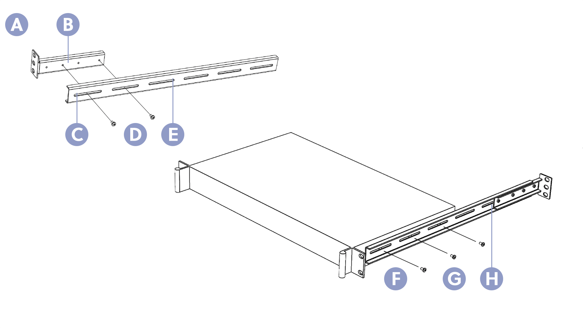
A. Connect the L-bracket to the outer rail, do not tighten until you adjust the overall rail length
B. L-bracket
C. Open slot
D. 6-32 screws
E. Outer rail
F. Set the depth and tighten the rail
G. 6-32 screws
H. After installing the rail into the rack, secure the back ears to the back of the cabinet
Install the rail mounting system
- Align the open slots on the outer rails with two screw holes on the L-bracket. Leave room to adjust the Lbracket position if necessary.
- Secure the L bracket to the rail with two 6-32 screws.
- Repeat steps 1 and 2 with the second rail and bracket.
- Extend the outer rail to match the depth of your cabinet.
- Align the open slots on the outer rail with the screw holds on the side of the GateWay device.
- Secure the outer rail to the GateWay device with two or three 6-32 screws.
- Repeat steps 4 through 6 with the other rail.
- Tighten all screws.
Set up the rack cabinet
- Mount the active GPS antenna and all LTE and Wi-Fi antennas, ensuring that all cables can reach the back of the GateWay device easily. Set up the antennas according to the manufacturer’s instructions. As part of this setup, you should also consider how the RF cables are routed from the antennas to the GateWay device.
- Plug the power cord into an outlet inside the rack cabinet.
- Connect one or two Ethernet cables in the rack cabinet.
- Pull all cables into the opening in the rack cabinet where you want to install the GateWay device.
Install the GateWay device
- Position the GateWay device at the front of the rack cabinet.
- Using the Mini-Circuits tool, screw the antennas to the SMA connectors on the back of the GateWay device. Make sure that the tool engages the SMA connector on the RF cable, not the hex lock nut on the chassis.
- Verify that you connected the active GPS antenna to the correct connector.
- Connect the power cord to the back of the GateWay device.
- Verify that your power source and fuse are adequate to meet the maximum power specifications.
- If necessary, perform one or more of the following actions:
- To connect to a LAN, connect an Ethernet cable to the LAN port on the back of the GateWay device. Add a label to indicate that the cable is for the LAN port.
- To connect to a WAN, connect an Ethernet cable to the WAN port on the back of the GateWay device. Add a label to indicate that the cable is for the WAN port.
- To connect the additional Ethernet ports, connect Ethernet cables to the ports on the back of the device. Add a label to indicate that the cables are for Ethernet ports 1 through 4.
- If you want to configure the device using the GateWay User Interface and you want to use a monitor with this tool, connect the monitor to the HDMI port or DisplayPort on the back of the device. Connect a keyboard and mouse to the USB ports. Alternatively, you can connect these peripherals using a KVM switch.
- Insert the GateWay device with all the cables attached into position in the rack cabinet.
- Secure the front ears on the GateWay device to the front of the cabinet.
- If necessary, adjust the position of the L-brackets on the rails so that the back ears reach the back of the cabinet.
- Secure the back ears on the rails to the back of the cabinet.
- Press the On/Off button.
For more information, visit support.dejero.com to read the Dejero GateWay M6E6 / M6E6F User Guide.
About the GateWay device
Without a monitor attached, when you press the On/Off button, the GateWay device runs through the start-up process and the Main screen appears.
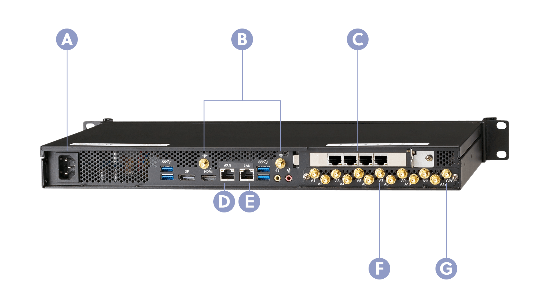
A. Power
B. Wi-Fi Antenna connectors
C. Additional Ethernet ports – The ports are numbered 1 through 4 (from left to right)
D. WAN port
E. LAN port
F. Antenna connectors
G. GPS connector
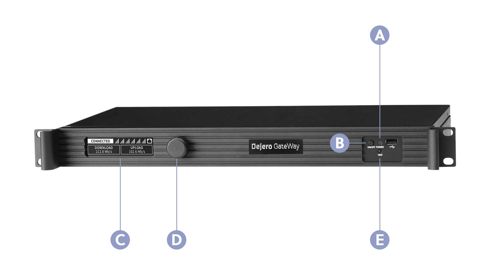
A. Power light
B. On/Off button
C. Front display screen
D. Dial
E. Hard disk activity light
Configure the GateWay device
After installing the GateWay device, log into Dejero Control as an administrator to configure and manage the device. Then, connect other devices to it (using the LAN or WAN ports or Wi-Fi) to access the internet. For more information, visit support.dejero.com to read the Dejero GateWay M6E6 / M6E6F User Guide.
Need help?
You can find more support information on the SupportHub at support.dejero.com. If you require additional help, please contact support at support@dejero.com.
Technical Support:
support@dejero.com
US & Canada (Toll Free): 1 866 808 3665, ext 2
International: +1 519 772 4824, ext 2